Introducing the NE555 Chip
Previously, we introduced various types of XBLW signal chain chips from Chip Bo Le. Today, we bring you the NE555 chip, which is widely used by electronics enthusiasts and serves a significant role. It is a small-scale integrated circuit used in many electronic products. The NE555 functions as a timer to form a time-based circuit, providing timing pulses to other circuits. Based on the NE555, several other products have been developed, such as the NE556, TLC555, and GT7555, which have the same structure and principles but enhanced applications and performance.
01 — NE555 Overview
The XBLW NE555's internal structure can be equivalent to 23 transistors, 17 resistors, and two diodes, forming comparators, RS flip-flops, and other units. Notably, three precision 5k resistors form a voltage divider, providing reference voltages for the upper and lower comparators. Thus, it is called the 555. The XBLW NE555 is manufactured using CMOS technology.
Pin Description and Internal Functional Block Diagram
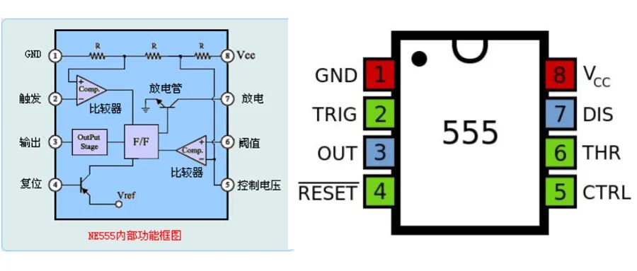
Main Features of the NE555
- Low static current, typical value 2.7mA
- Chip disable input allows IC power down
- Low static current during power down, typical value 65uA
- Can drive various impedance speakers above 8Ω
- Output power exceeds 250mW with a 32Ω load
- Low distortion, 0.5% TYP
- Gain adjustable from 0dB to 46dB in the voice frequency band
- Adjustable duty cycle
- Package forms: SOP8/DIP8
Key Operating Modes
The XBLW NE555 has three commonly used operating modes: monostable, astable, and oscillator mode.
1. Monostable Mode:
In monostable mode, the output pin remains low until an input trigger pulse arrives. Once the trigger pulse arrives, the output pin switches to high, staying high for a set period before returning to low.
2. Astable Mode:
In astable mode, the output pin alternates between high and low states, controlled by the power supply voltage. When the power supply voltage exceeds a certain threshold, the output pin is high; when it falls below another threshold, the output pin is low.
3. Oscillator Mode:
In oscillator mode, the XBLW NE555 can function as a simple oscillator to generate square wave signals. The frequency and duty cycle of the output square wave can be controlled by adjusting external resistors and capacitors.
Application Circuits
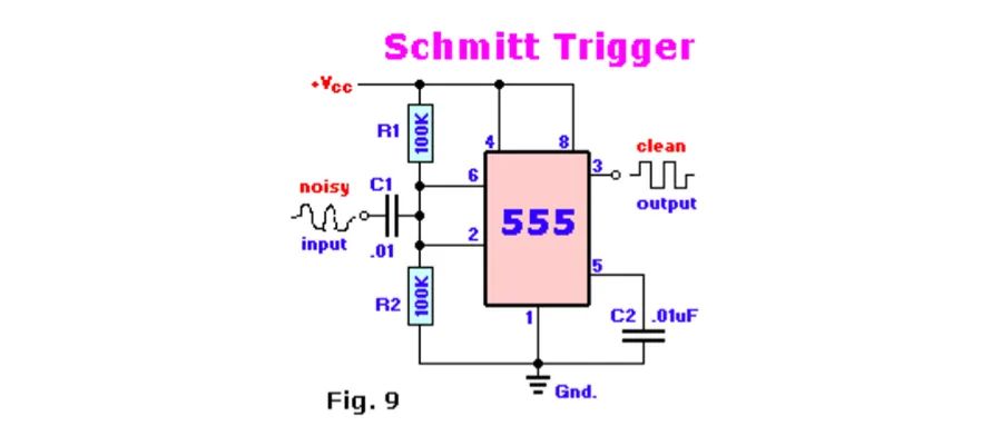
[Insert Image: Schmitt Trigger Circuit]
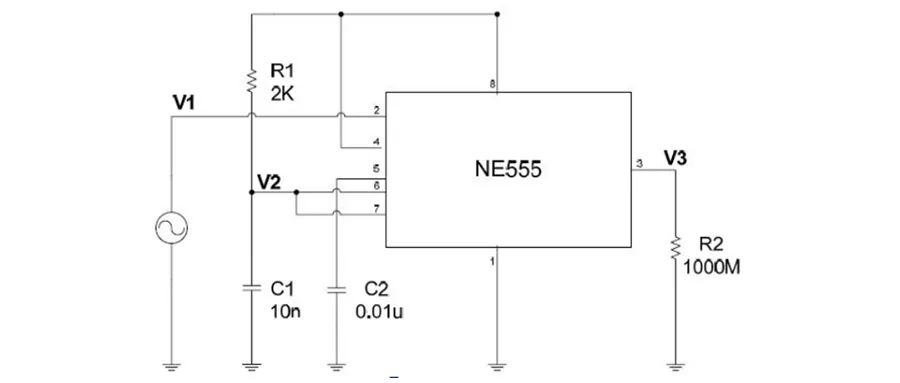
[Insert Image: Monostable Circuit Trigger]
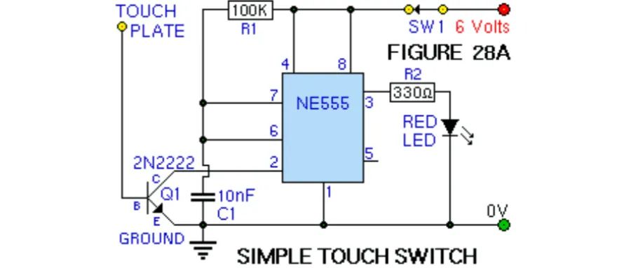
[Insert Image: Easy Touch Switch Circuit]
02 — Application Fields
- Turn indicator circuits for all types of vehicles and bicycles.
- Built-in strobe light/SOS signal circuits (for signaling danger or need for help).
- Controlling wiper motors to produce reciprocating motion.
- Indicator lights for automobiles (using relay-based flashing LED circuits).
- Input for applications requiring timed pulses, such as counters using 4017 and 4026 ICs.
- Pulse Width Modulation (PWM) and Pulse Position Modulation (PPM)
- Duty cycle oscillators
- Light dimmers
- Providing accurate time delays
- As a trigger element
- Digital logic probes
- Analog frequency meters
- Quad timer applications
- Pulse, waveform, and square wave generation
- Stepped tone and burst tone generators and linear ramp generation
- Tachometers and temperature measurement
- Can be used as monostable multivibrators and astable multivibrators
- Frequency dividers
- Schmitt triggers
- Cable testers
- Pulse detectors
- Wiper speed control
- Timed power on/off
- Delay generation, precise timing, and sequential timing
The XBLW NE555 can form a wide variety of application circuits, making it widely used in the electronics field. Derived from it are the dual-timer XBLW NE556 and the low-power XBLW GT7555 chips, which facilitate use in other fields. The XBLW NE555 can replace SE555 and LM555, offering stable performance and cost-effectiveness, making it an ideal choice for replacement and new project solutions.
Recommend News
-
Phone
400-9682 003

