
Op-amp power supply mode selection pitfalls guide: Single power supply vs. dual power supply comparison
In operational amplifier circuit design, the choice of power supply method is often the first decision to be made. This is not merely a matter of different power supply pin connections, but a crucial choice that fundamentally affects the circuit architecture , signal processing capabilities , and design complexity .
I. Basic Concepts: What are the two power supply methods?
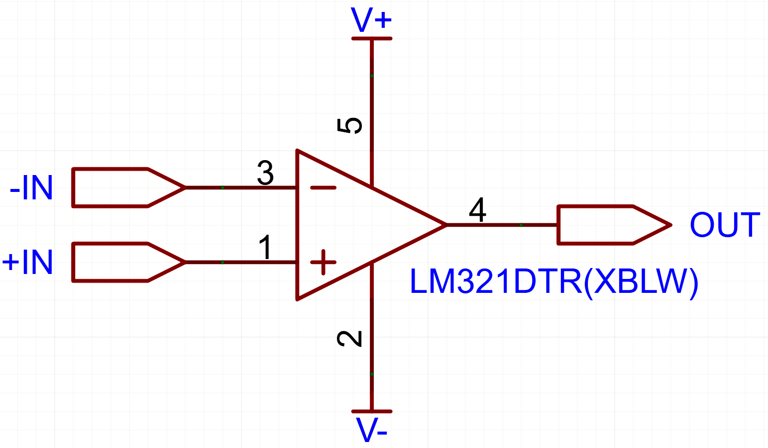
Dual power supply: Consists of apositive power supplyand anequivalent negative power supply, with common combinations being±15V, ±12V, and ±5V. The common connection point of the two power supplies provides astable,low-impedancezero reference point. Both input and output voltages arereferenced to this "ground,"allowing signals to swing symmetrically between positive and negative voltages.
Single power supply: The op-amp's power supply pins are connected to both the positive power supply and ground, with only one positive power supply. The common voltage is5V, but systems with 3V or even lower are now also available.
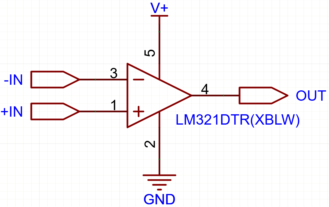
It's important to note that the pin markings on an op-amp cannot be used to determine whether it's a "single-supply" or "dual-supply" amplifier . Some datasheets label the pins as V+ and V-, while others label them as VCC and GND; this is simply a difference in convention between manufacturers . What truly determines whether it can be used is whether the voltage difference between the two power supply pins is within the absolute maximum supply voltage range specified in the datasheet .
In principle,all operational amplifiers can be powered by a single power supply; the key issue lies in how to set the reference point for the signal ground.
II. Core Design Differences
1. Bias and Virtual Ground
An operational amplifier is essentially adual-supply device. In a dual-supply configuration,the signal oscillates symmetrically with0V as a reference, requiring no additional bias circuitry.
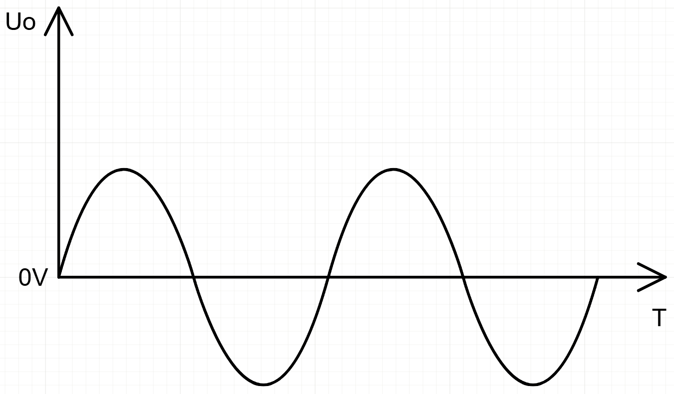
However, in a single-supply system, since there is no negative power source, the input signal (especially AC signals) must bebiased by a DC biastoallow the signal to swing correctly between the positive power source and ground. This bias voltage is usually set toVCC/2 and is called "virtual ground".
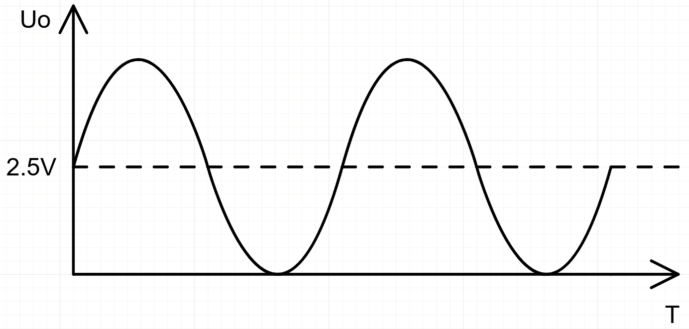
Virtual ground is typically generated usinga voltage divider circuit composed of two resistors of equal value. However, in multi-stage amplifier circuits, the DC bias of each stage is amplified by the subsequent stage, which may cause the circuit to exceed its normal operating voltage range. Therefore,DC blocking capacitors are usually added between stages.
The value of the bias resistor needs tobe balanced between power consumption and input bias current error:100kΩ is usually selected for 15V or 12V single power supply, while a lower value is required for 5V single power supply.
2. Input common-mode voltage range
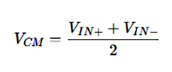
The input common-mode range of dual-supply power supplies is typically designed to besymmetrically distributedbetweenthe positive and negative supply voltages, allowing for more flexible acceptance ofbipolar signals.
The input common-mode range of a single-supply op amp must be well matched with the bias voltage.Many single-supply op amp designs set the input common-mode range close to ground and positive power supply. When using it, be careful not to exceed the limit.
3. Adaptability to signal types
Dual power supply: Naturally suited for handlinginput signals with both positive and negative voltages. The input signal range is typically wider, and in high-precision and wide dynamic range applications (such as instrumentation circuits),the dual power supply design prevents the op-amp from approaching its supply limits, thus reducing distortion.In high-speed signal processing circuits, dual power supplies canprovide greater bandwidth and output swing.
Single power supply: More suitable for processingsensor output signals above ground potential. For input signals containing negative voltages, although they can be "lifted" to the positive voltage range by applyinga bias voltage,the trade-off is that when the input is 0V, the output relative to GND is difficult to reach an absolute 0V. If an amplifier circuit is connected afterward, this tiny offset may be amplified into a catastrophic error.

Conclusion
The choice between a single power supply and a dual power supply essentially involves a trade-off between design complexity , signal dynamic range , system cost , and power consumption . Dual power supply solutions offer significant advantages in performance and design convenience, while single power supply solutions are irreplaceable in terms of cost and system integration . With the increasing prevalence of low-voltage portable devices, single-supply op-amp design has become a fundamental skill that engineers must master —and understanding the essential differences between single-supply and dual-supply designs is the first step in mastering this fundamental skill.
Recommend News



Follow Us


-
Phone
400-9682 003