
XBLW XOPA340 / XOPA2340 / XOPA4340 CMOS Precision Op‑Amplifier Technical Article
In signal‑conditioning and amplification applications, hardware engineers constantly make trade‑offs among bandwidth, noise, power consumption and cost. XBLW’s XOPA340 (single‑channel), XOPA2340 (dual‑channel) and XOPA4340 (quad‑channel) CMOS precision op‑amps deliver an optimum high‑performance, cost‑effective solution for industrial‑control, automotive‑electronics and battery‑powered equipment with 11 MHz bandwidth, 8 nV/√Hz low noise, 750 µA low quiescent‑current and rail‑to‑rail input‑output performance.
1. New‑Product Introduction: XOPA340 / XOPA2340 / XOPA4340 Series
XOPA340/XOPA2340/XOPA4340 are XBLW’s new‑generation general‑purpose low‑power op‑amps built on advanced CMOS technology. They achieve 11 MHz gain‑bandwidth‑product and 11 V/µs slew‑rate at very low quiescent‑current. Their ultra‑low noise (8 nV/√Hz@10 kHz) and low input‑bias‑current (typical 1 pA) make them ideal for high‑impedance‑source conditioning such as photodiode amplifiers and piezoelectric‑sensor interfaces.
2. Key Specifications
- Wide bandwidth: 11 MHz unity‑gain bandwidth for high‑frequency‑signal conditioning
- Low noise: 8 nV/√Hz@10 kHz for high‑precision‑measurement applications
- Low offset voltage: Max ±0.35 mV
- Low power consumption: 750 µA quiescent‑current per channel
- Rail‑to‑rail I/O: Input range covers supply rails; output swings close to supply rails
- Wide supply‑voltage range: 1.8 V ~ 5.5 V
- Enhanced EMI filtering: Integrated input‑EMI filter for improved noise‑immunity
- High ESD protection: 4 kV HBM, suitable for industrial‑grade applications
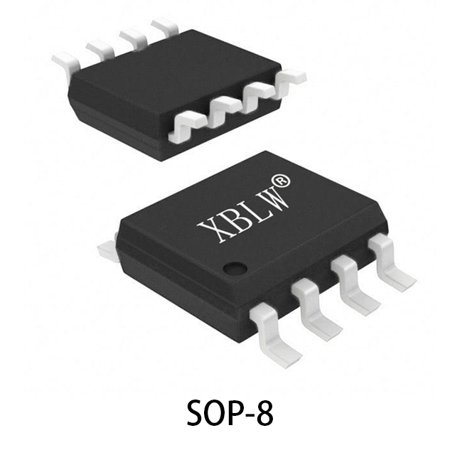
- Multiple package options: SOT23‑5, SOP‑8, MSOP‑8, SOP‑14, TSSOP‑14
3. Application Scenarios
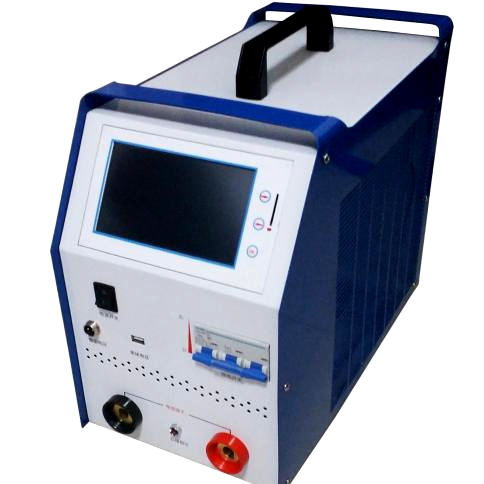
- Automotive HEV / EV inverter and motor‑control systems
- Battery‑powered instrumentation
- ADAS sensor‑signal conditioning
- Motor phase‑current sensing
- Active‑filter circuits
- Photodiode amplification
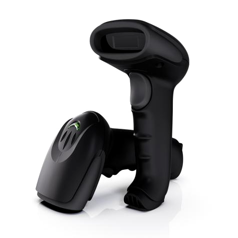
- Barcode scanners
4. Circuit‑Design Guidelines
Differential‑Amplifier Circuit
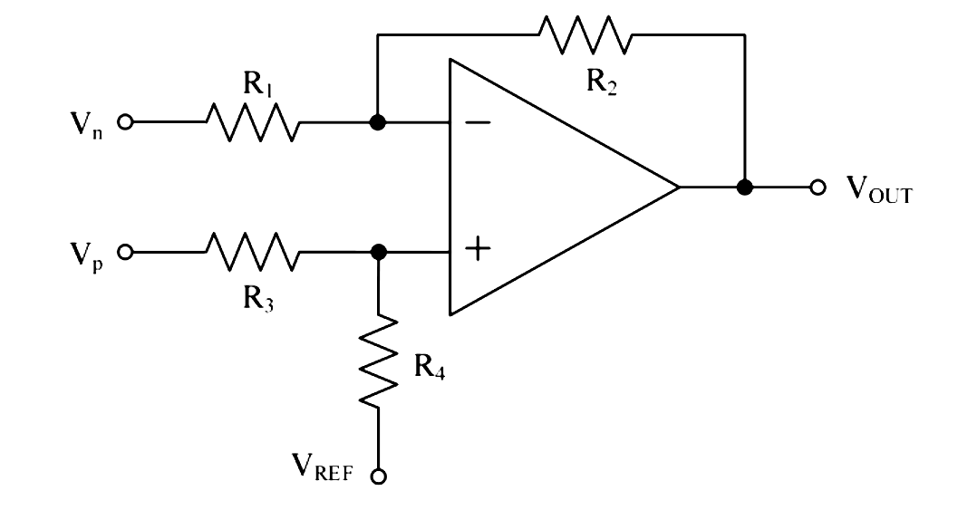
Thanks to high bandwidth and low‑noise performance, XOPA340/XOPA2340/XOPA4340 are well‑suited for precision differential‑amplifier designs. The figure shows a typical differential‑amplifier circuit converting differential‑input signals to single‑ended output while suppressing common‑mode noise. High common‑mode‑rejection‑ratio is achieved by matching external resistors (R4/R3 = R2/R1).
5. Instrumentation‑Amplifier Circuit

XOPAx340 devices excel at sensor‑signal conditioning within battery‑powered systems. The above figure shows a two‑op‑amp instrumentation‑amplifier built with XOPAx340 op‑amps. This circuit is intended for applications requiring common‑mode‑noise rejection at high‑gain settings. Reference voltage (VREF) shall be driven by a low‑impedance source. For single‑supply applications, VREF is typically set to Vs/2.
6. Device‑Selection Guide
Part Number | Channels | Package | Bandwidth | Iq | Offset Voltage | Typical Use‑Case |
XOPA340NA | Single | SOT23‑5 | 11 MHz | 750 µA | ±0.35 mV | General‑precision amp, portable equipment |
XOPA340UA | Single | SOP‑8 | 11 MHz | 750 µA | ±0.35 mV | Low‑noise signal‑conditioning |
XOPA2340UA | Dual | SOP‑8 | 11 MHz | 750 µA | ±0.35 mV | Differential‑amp, filter applications |
XOPA2340EA | Dual | MSOP‑8 | 11 MHz | 750 µA | ±0.35 mV | Space‑constrained high‑performance designs |
XOPA4340UA | Quad | SOP‑14 | 11 MHz | 750 µA | ±0.5 mV | Multi‑channel signal‑conditioning |
XOPA4340EA | Quad | TSSOP‑14 | 11 MHz | 750 µA | ±0.5 mV | High‑density multi‑channel designs |
7. PCB Layout Recommendations
To realize full performance of XOPA340/XOPA2340/XOPA4340, observe these PCB‑layout best‑practices:
1. Power‑supply decoupling: Place 0.1 µF ceramic capacitor close to each power‑supply pin to minimise power‑noise coupling.
2. Avoid thermocouple effects: Use homogeneous conductor materials on input paths and maintain uniform temperatures to prevent Seebeck‑voltage‑induced offset errors.
3. Input‑output isolation: Prevent parallel input‑output traces to reduce parasitic‑capacitance feedback.
4. Ground‑plane design: Use solid ground plane for low impedance; avoid ground‑loop formation within sensitive input sections.
5. Thermal management: For multi‑channel or high‑output‑current applications, provide adequate thermal vias and copper‑pour areas.
VIII. Comparison of alternative models available internationally
Model | Brand | Bandwidth | Noise | Static current | Imbalanced voltage | Features and Specifications |
XOPA340 | Chen Bule | 11 MHz | 8 nV/√Hz | 750mA | 0.35 mV | Low noise, rail-to-rail, low power consumption |
OPA340 | TI | 5.5 MHz | 25 nV/√Hz | 750mA | 0.15 millivolts | Generally, low power consumption and low bandwidth. |
OPA365 | TI | 50 MHz | 4.5 nV/ √Hz | 4.6 milliamperes | 0.4 mV | High bandwidth, but with a relatively high power consumption. |
AD8605 | ADI | 10 MHz | 8 nV/√Hz | 1 milliamp | 80 μV | Low noise, lower deviation voltage |
MAX44248 | ADI | 1 MHz | 50 nV/ √Hz | 90 microamperes | 2uV | Extremely low power consumption, low bandwidth. |
MCP6V01 | Microchip | 1.3 MHz | 45 nV/√Hz | 300 microamperes | 2uV | Non-modulated, narrow bandwidth |
The XOPA340/XOPA2340/XOPA4340 offers a good balance between 11MHz bandwidth, low noise, and low power consumption, making it particularly suitable for battery-powered devices and industrial control systems that require both dynamic range and precision.
Nine. Summary.
The XOPA340/XOPA2340/XOPA4340 series of CMOS operational amplifiers offer engineers a high-performance, cost-effective solution for analog signal conditioning, thanks to their 11MHz bandwidth, 8nV/√Hz low noise, and 750uA low power consumption, as well as their rail-to-rail capabilities.
Recommend News


Follow Us


-
Phone
400-9682 003