
XBLW Product Application Guide for Current‑Sensing Solutions
Current sensing is the core for electronic‑circuit detection and protection. Through real‑time sampling, accurate conversion and signal analysis of loop current, it provides critical data support for system safety protection and closed‑loop control. Widely used in motor drive, industrial measurement & control and other fields, it is essential for reliable equipment operation. Two mainstream sensing methods are available: shunt‑resistor sensing based on Ohm’s law, and Hall‑effect isolated sensing.
Shunt‑Resistor Sensing:
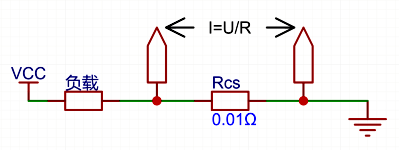
l Low‑Side Current Sensing
Sense resistor is placed between load and ground; amplifier measures voltage drop across the low‑side sense resistor.
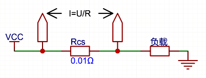
l High‑Side Current Sensing
Sense resistor is placed between power supply and load; amplifier measures voltage drop across the high‑side sense resistor.
Isolated Sensing:
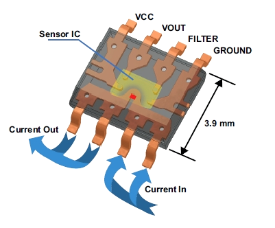
l Hall‑Effect Current Sensing:
Adopt XBL GT712 Hall‑effect sensor or current transformer for galvanically‑isolated measurement, suited for high‑voltage systems.
1. Basic Principle of Current‑Sense Amplifiers
A current‑sense amplifier is a differential amplifier dedicated to current measurement. Its core function is to amplify small voltage signals across the sense resistor (shunt) to levels suitable for ADC sampling. It works according to Ohm’s law: calculate current value by measuring voltage drop across a known‑value sense resistor.
Key performance parameters:
· Common‑Mode Voltage Range
· Input Bias Current
· Gain Error & Drift
· Bandwidth & Response Time
· CMRR (Common‑Mode Rejection Ratio)
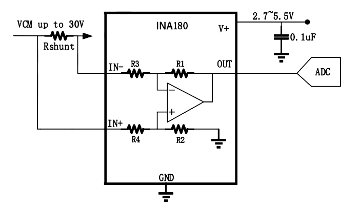
INA180/181 current‑sense amplifiers integrate precision‑matched resistor networks and provide fixed gains (e.g. 20V/V, 50V/V, 100V/V), significantly reducing temperature drift and gain error.
2. Low‑Side Current‑Sensing Solution
2.1 Sensing Principle & Implementation
For low‑side sensing, the sense resistor is connected in series between load and ground. A current‑sense amplifier or operational amplifier amplifies voltage drop across the resistor.
l Design based on INA180/181:
Schematic:
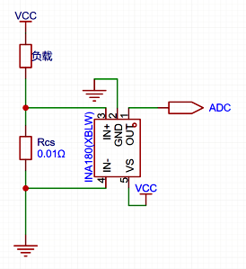
I_load = Vout / ( R_cs × Gain )
l Design based on LMV321 (operational amplifier):
Schematic:
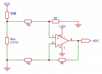
Typical configuration: differential‑amplifier structure:
Vout = (1 + Rf/Rg) × ( I_load × R_cs )
2.2 Pros & Cons
· Advantages:
Simple circuit, low cost
Low requirement for op‑amp common‑mode input range
Single‑supply general‑purpose op‑amps can be directly used
Ground‑referenced, straightforward measurement system
· Disadvantages:
Ground‑path integrity is compromised; load is not directly grounded
Cannot detect load‑to‑ground short‑circuit faults
Voltage drop across sense resistor reduces effective load voltage
Ground‑line disturbance degrades measurement accuracy under high‑current conditions
2.3 Application Scenarios
· Cost‑sensitive low‑voltage applications
· Portable devices with relatively small current
· Applications where ground‑short detection is not required

3. High‑Side Current‑Sensing Solution
3.1 Sensing Principle & Implementation
For high‑side sensing, the sense resistor is placed between power supply and load, measuring current directly on the power rail.
Design based on INA180/INA181:
Typical application circuit:
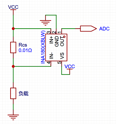
I_load = Vout / ( R_cs × Gain )
INA180/INA181 Key Specifications:
· Wide common‑mode voltage range: -0.2V ~ +30V
· Fixed‑gain options: 20V/V, 50V/V, 100V/V, 200V/V
· Low input bias current: -6µA
· High CMRR: 100dB
· Operating‑temperature range: -40℃ ~ +125℃
3.2 Pros & Cons
Advantages:
· Preserves system‑ground integrity
· Capable of detecting load‑to‑ground short‑circuit faults
· Suited for high‑current and high‑precision measurements
· Integrated solutions deliver high accuracy and low drift
Disadvantages:
· Requires amplifier with high common‑mode rejection ratio
· Relatively higher cost
· Demands high common‑mode input capability for amplifiers
3.3 Application Scenarios
· Power‑supply systems requiring ground‑short‑fault monitoring
· High‑current applications
· Use‑cases demanding high measurement accuracy
· Multi‑rail systems requiring common‑ground integrity
4. Device Selection Recommendations
4.1 Devices for Low‑Side Sensing
· General‑Purpose: XBLW LM321, XBLW LM358
o Low‑cost, single / dual channel
o Suitable for consumer products with moderate‑accuracy requirements
· Precision‑Grade: XBLW LMV321, XBLW INA180, XBLW INA181
o Low offset voltage, low drift
o Suited for portable devices requiring higher accuracy
4.2 Devices for High‑Side Sensing
· General High‑Voltage: XBLW INA180, XBLW INA181
o Up to 30V common‑mode voltage, multiple gain options
o Ideal for 12V / 24V industrial and automotive systems
4.3 Selection Decision Matrix
Low‑Side Sensing | High‑Side Sensing | |
Cost | Low | Medium‑High |
Accuracy | Moderate | High |
Circuit Complexity | Simple | Medium |
Fault‑Detection Capability | Weak | Strong |
Grounding Impact | Yes | None |
Recommended Applications | Consumer‑Electronics, Battery‑Powered Devices | Industrial‑Control, Automotive‑Electronics, Power‑Supply Systems |
5. Summary & Design Recommendations
1. Define Key Requirements:
o Measurement range and accuracy requirements
o System voltage and common‑mode voltage
o Fault‑detection requirements
o Cost budget and form‑factor constraints
2. Select Sensing Location:
o If ground‑path integrity or short‑circuit monitoring is required → choose high‑side sensing
o Cost‑sensitive, low‑voltage low‑current → consider low‑side sensing
o High‑voltage isolation required → adopt isolated sensing solution
3. Device Selection Guidelines:
o Select amplifier according to maximum common‑mode voltage
o Calculate sense‑resistor value from current range and ADC resolution
o Evaluate drift impact on long‑term accuracy
o Assess bandwidth and noise‑immunity requirements
4. PCB Layout & Routing Recommendations:
o Use Kelvin (4‑wire) connection for sense resistor
o Place amplifier close to sense resistor
o Route sensitive analog traces away from power‑conducting paths
o Add appropriate filtering and protection circuits
Modern integrated current‑sense amplifiers such as INA180/181 greatly reduce design effort and improve system reliability. For most industrial and automotive applications, high‑side sensing is the preferred solution. XBLW INA180/181 series are developed for high‑side current‑sensing and protection requirements, delivering more convenient and accurate current‑measurement performance compared with alternative solutions.
Recommend News

Follow Us


-
Phone
400-9682 003