
【Application】XBLW LM2577 Boost DC/DC‑Converter for Bluetooth‑Speaker Power‑Supply
Within the compact mechanical design of portable Bluetooth speakers, an efficient, stable power‑system delivering sufficient power capability is the cornerstone for long battery‑life and high‑quality audio output. XBLW LM2577 is a classic 52 kHz, 3A Boost DC/DC converter. Featuring wide input‑voltage range, high conversion efficiency and simple peripheral‑circuitry, it acts as an ideal “energy bridge” between battery and power‑amplifier ICs, enabling small‑form‑factor yet high‑performance Bluetooth‑speaker designs.
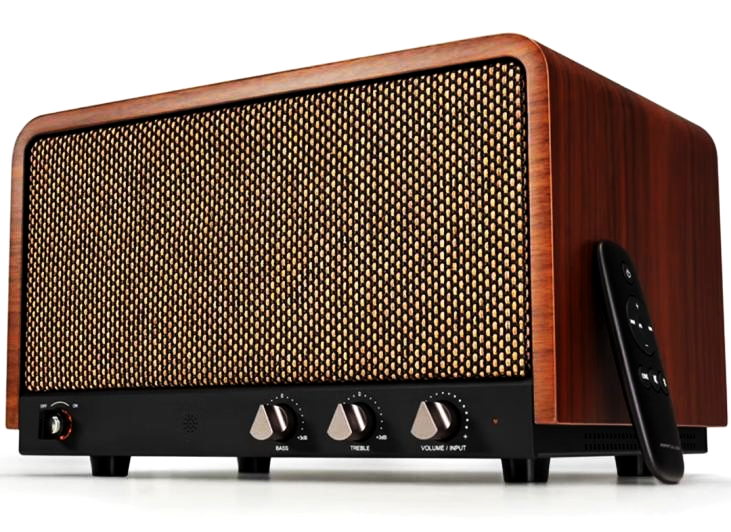
Application diagram of XBLW LM2577 for Bluetooth‑speaker
1. Application Introduction: Solve Power‑Supply Pain‑Points of Bluetooth Speakers
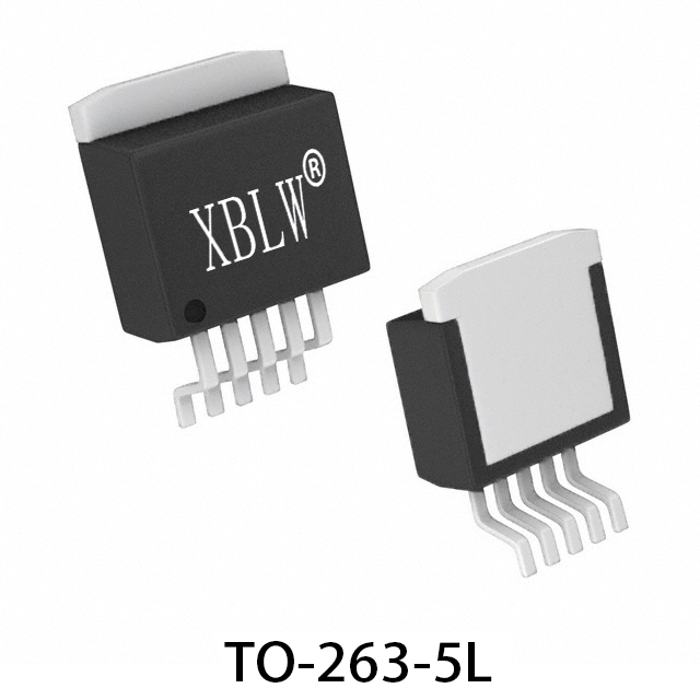
Portable Bluetooth speakers are typically powered by 3.7V lithium‑ion battery. The battery voltage cannot directly satisfy the higher‑voltage requirement of most Class‑D power‑amplifier ICs for larger output power and improved dynamic range. The XBLW LM2577 is a monolithic IC integrating a 3A, 65V‑rated NPN power switch, suited for boost, flyback and forward switching‑regulator designs. Only a few external components are required to build a complete boost power‑supply, significantly reducing system cost and complexity. Fixed‑output (12V,15V) and adjustable‑output versions are offered in TO‑220‑5 and TO‑263‑5 packages, well‑suited for Bluetooth‑speaker products.
2. Core Advantages for Bluetooth‑Speaker Applications
l Battery‑compatible wide input range: 3.5V~40V input range covers the full discharge curve of lithium‑ion cells (from full charge to cut‑off voltage). It guarantees stable amplifier supply‑voltage even when battery capacity drops, without volume degradation.
l High‑efficiency conversion extends playback time: Typical efficiency exceeds 80%, greatly reducing power loss during boost conversion. More battery energy is delivered to loudspeakers to improve playback duration.
l 3A continuous output capability: Easily handles peak‑current demands of power amplifiers under high‑volume conditions, ensuring undistorted sound and uncompressed dynamic range.
l Small footprint & cost‑effective: Fixed‑frequency and integrated‑switch design requires only few external components including inductor, diodes and capacitors. It is ideal for layout inside limited internal speaker space and keeps overall BOM cost under control.
l Built‑in protections improve reliability: Integrated thermal shutdown and current‑limit functions effectively prevent permanent damage caused by overload, short‑circuit or high ambient temperature and enhance product durability.
3. Typical Power‑Supply Architecture
For typical single‑cell lithium‑ion‑powered Bluetooth speakers, the power‑supply architecture is shown below:
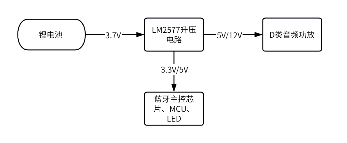
Note: Boosted main rail (e.g.12V) directly feeds power amplifier. Other low‑voltage chips inside system (Bluetooth module, MCU etc.) get their supply from this high‑voltage rail via post‑stage LDO or small‑current step‑down circuits, realizing multi‑rail requirements from single‑cell battery.
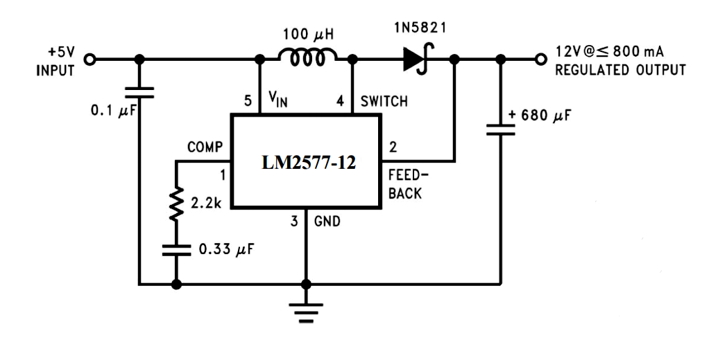
Application schematic (boost to 12V as example):
4. Key‑Component Selection & Design Guidelines
1. Output capacitor (Cout):
- Function: Beyond filtering, it supplies instantaneous current during large dynamic audio bursts and suppresses supply‑voltage droop, which is critical for low‑frequency punch and transient‑response performance.
- Selection: Low‑ESR electrolytic capacitor is recommended, complemented by multiple small‑value MLCC for high‑frequency decoupling. Low‑ESR is key to reduce power‑supply noise within audio frequency band.
2. Freewheeling diode (D1):
- Schottky diode is mandatory. Its very low forward voltage drop (~0.3‑0.5V) helps minimize switching loss and improve overall system efficiency.
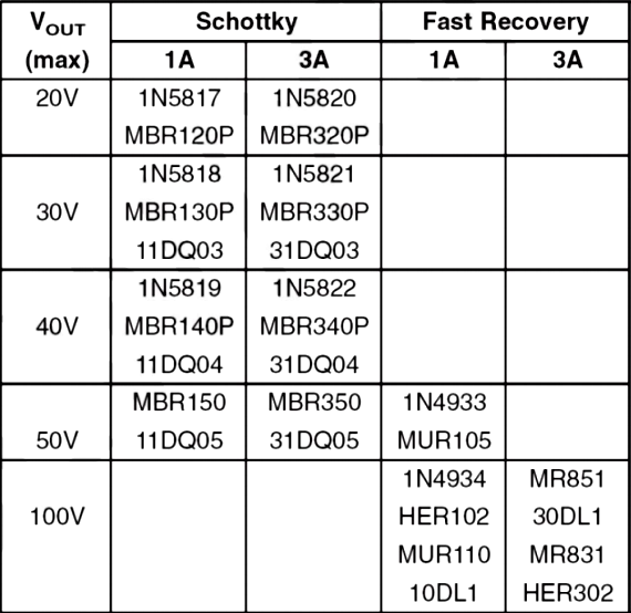
Part‑number example: For 12V output, 1N5822(40V) for 1A‑level; for 3A‑level choose SMD Schottky such as SK34 / SR304(40V). Reverse‑voltage rating shall exceed maximum output voltage.
3. Inductor selection & PCB layout notes:
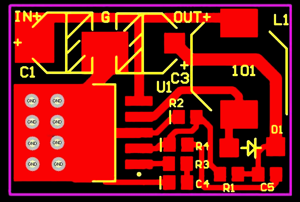
l Minimize large‑current loop area: The high‑frequency switching loop “Battery+ → Inductor → IC SW pin → GND” must be kept as small as possible to reduce EMI electromagnetic radiation.
l Noise‑sensitive‑node isolation: FB feedback trace must be routed away from noise sources such as inductors and diodes.
l Thermal handling: Even with decent efficiency, heat will be generated under heavy load. Fully solder the exposed thermal pad onto large copper area on PCB and connect via multiple vias to inner‑layer or back‑side ground copper plane for heat dissipation.
5. Summary
For portable Bluetooth‑speaker designs, XBLW LM2577 delivers an efficient, reliable and cost‑effective battery boost solution. It solves the bottleneck of insufficient single‑cell lithium‑ion voltage, enabling compact speakers to drive high‑quality power‑amplifier ICs requiring higher supply rails for louder volume, richer detail and stronger low‑frequency performance. Its high efficiency and comprehensive protection features directly contribute to long battery‑life and high product reliability. Through careful external‑component selection and optimized PCB layout, engineers can fully exploit XBLW LM2577 performance to bring users long‑lasting, pleasant music‑playing experience.
Recommend News

Follow Us


-
Phone
400-9682 003