
【Application】XBLW 24C02/24C04/24Cxx: Non‑Volatile Memory Solution with Million‑Cycle Erase‑Write Endurance
In embedded systems and smart devices, small‑capacity, re‑writable non‑volatile memory always plays a critical role. XBLW 24Cxx serial EEPROM series features standardized interface, stable performance and ultra‑low power consumption. It is the preferred choice for storing configuration parameters, user settings, operation logs and other data. It is widely adopted in consumer electronics, industrial control and IoT equipment.
1. Product Overview
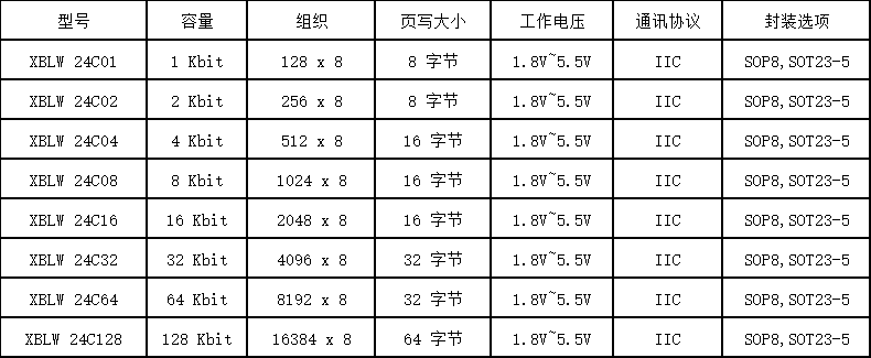
24C02/24C04/24Cxx series are serial electrically erasable programmable memory (EEPROM) based on the I²C bus protocol, supporting long‑term data retention after power‑off. Compact packages such as SOP8, SOT23‑5 are available to fit various space‑constrained applications. Wide operating voltage range: 1.8V~5.5V, compatible with 3.3V and 5V systems for excellent power‑supply adaptability. This series covers multiple densities from 1K‑bit to 128K‑bit. Common part‑numbers include:
2. Core Advantages
l Standard I²C Interface: Only two signal lines (SCL, SDA), which greatly saves MCU pin resources.
l High Reliability: Supports 1 000 000 erase‑write cycles and 100‑year data retention to guarantee long‑term data stability.
l Wide‑Voltage Operation: 1.8V~5.5V, suitable for battery‑powered or low‑power devices.
l Built‑in Write‑Protection: Hardware WP write‑protect pin prevents accidental write operations.
l Page‑Write Capability: Supports multi‑byte page‑write operations for improved write efficiency.
l Multiple Address Options: Multi‑device bus addressing via A0/A1/A2 pins for flexible expansion.
3. Typical Application Scenarios
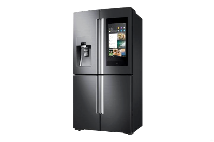
Smart Home Appliances: Store parameters such as washing‑machine modes, air‑conditioner settings and user preferences.
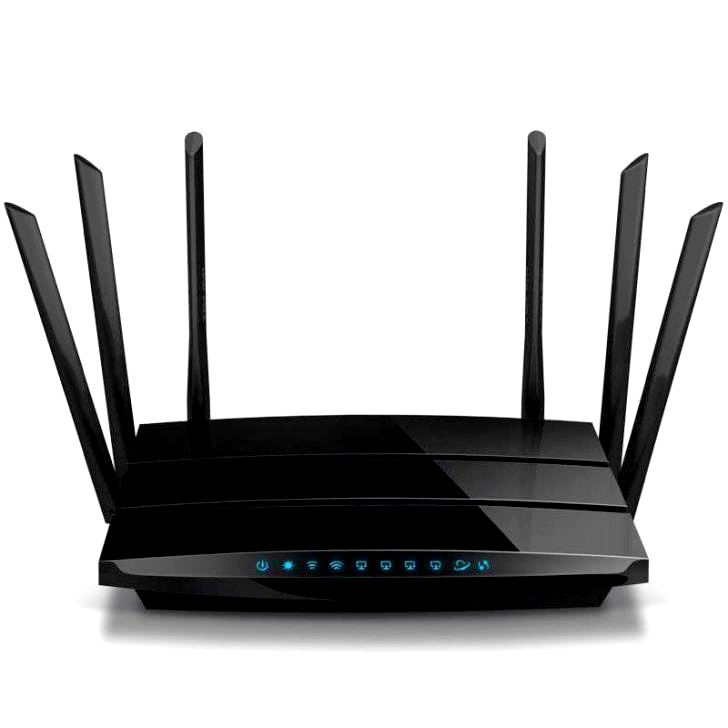
IoT Terminals: Save sensor calibration data, node‑ID identifiers and network‑configuration information.
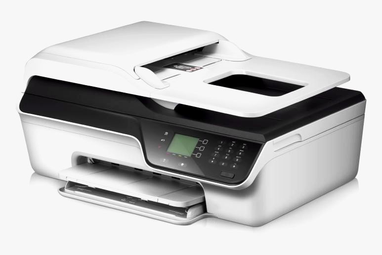
Consumer Electronics: For example, printer configuration storage, digital photo‑frame image‑index storage, audio‑device sound‑effect parameter storage.
4. Typical Application‑Circuit Design Guidelines
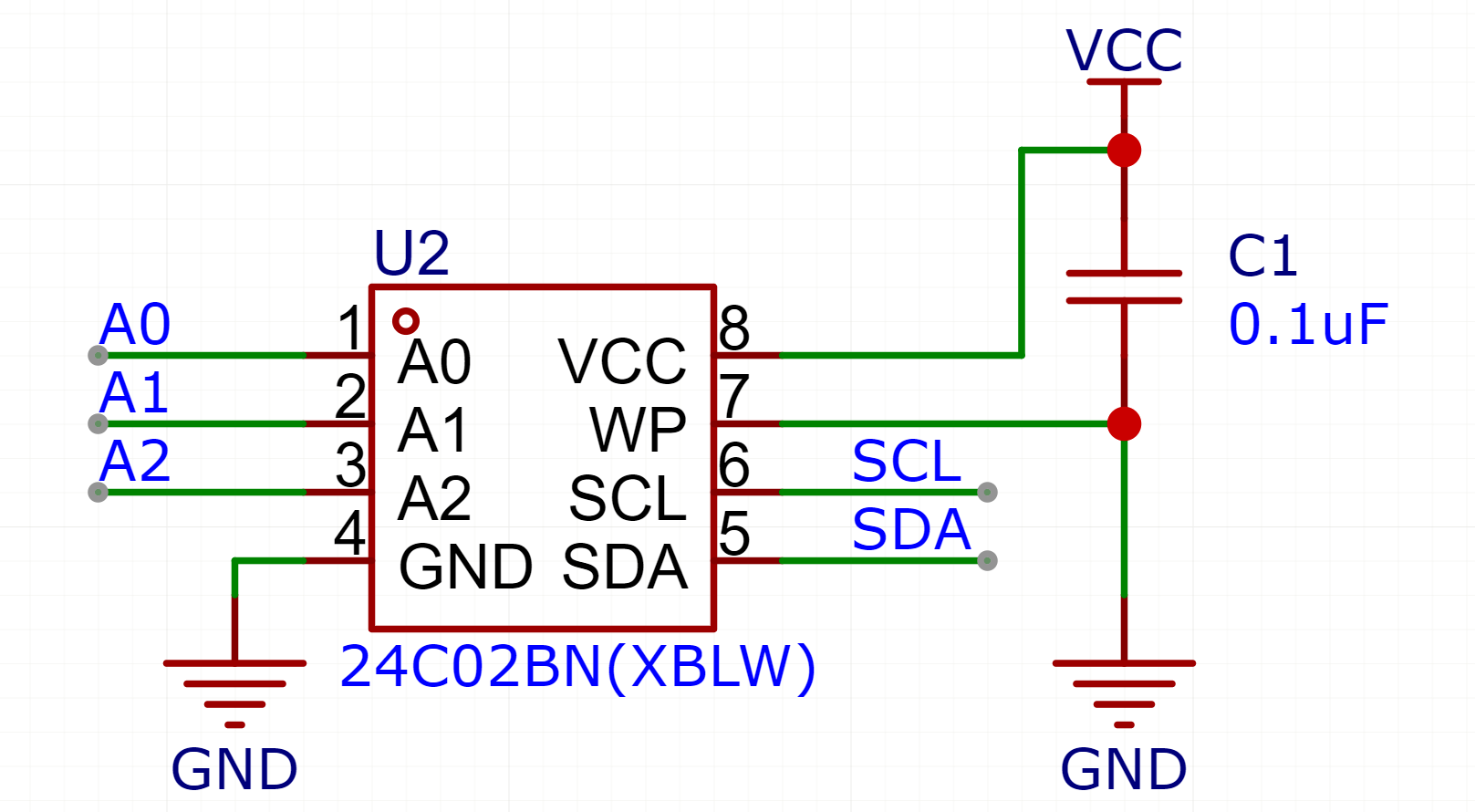
Basic Wiring Example:
VCC: Connect to 1.8V~5.5V power supply
GND: Connect to ground
SCL: Connect to MCU I²C clock line
SDA: Connect to MCU I²C data line (pull‑up resistor required, typically 4.7kΩ)
A0/A1/A2: Address‑selection pins. Logic level defines the device I²C slave address.
WP: Write‑inhibit at high level, write‑enable at low level
> Design Tips:
> When multiple EEPROMs share one bus, set distinct addresses via A0/A1/A2 pins.
> It is recommended to add series small‑value resistors (e.g. 100Ω) on SDA / SCL lines to suppress signal ringing.
5. Summary
XBLW 24C02/24C04/24Cxx series EEPROM is a classic choice for small‑capacity non‑volatile‑memory designs, featuring standardized interface, high reliability, low power consumption and minimal peripheral circuitry. Whether for cost‑sensitive consumer products or industrial equipment working under harsh conditions, it delivers stable, flexible and easy‑to‑integrate memory solutions, helping engineers rapidly realize product functions and improve overall‑system reliability.
Recommend News

Follow Us


-
Phone
400-9682 003