
Explore the XBLW LM4040 Voltage Reference Module: The Ideal Choice for High-Precision Measurement
In precision measurement and low-power design, the accuracy of the voltage reference directly determines the system's upper limit. Chiptel's LM4040 parallel voltage reference features an extremely simplified "2-pin + 1 resistor" architecture, making it a classic choice for engineers to achieve high-precision references. This paper approaches from a design perspective, reviewing key parameter calculations, error analysis, and layout points.
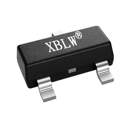
1. Core Selection Parameters
l The XBLW LM4040 offers five fixed output voltages: 2.5V, 3.0V, 3.3V, 4.096V, and 5.0V.
l Accuracy grades: Class A ± 0.1%, Class B ±0.2%, Class C ± 0.5%, Class D ± 1.0% (@25°C).
l Temperature coefficient: A/B/C grade 100ppm/°C, D grade 150ppm/°C.
current: minimuml Operating 60μA, maximum 15mA.
封装:l SOT-23-3、SC70-5、TO-92。
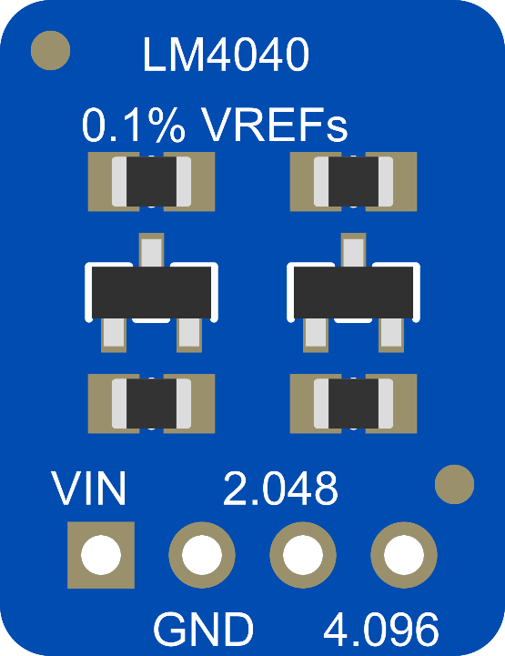
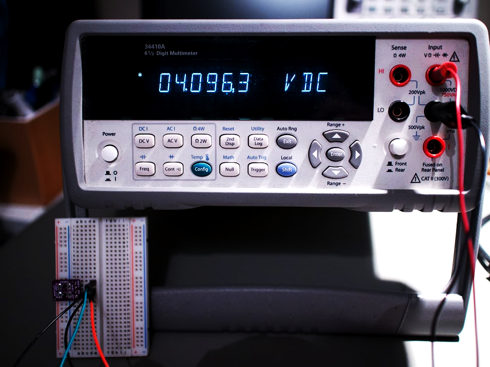
Design tip: A 12-bit ADC with 4.096V power supply can directly achieve 1mV/LSB, eliminating the need for floating-point conversion.
2. Current limiting resistance calculation (the most critical design step)
The LM4040 requires only one external resistor Rs to connect the input voltage to the cathode. Calculation formula:
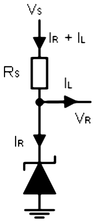
RS=(V S-VR)/(IL+IR)
I
R: Current flowing into the LM4040 cathode (must be greater than the minimum operating current RMIN, less than 15mA).
I: Load currentL
Practical Case:
Using XBLW LM4040AIZ-4.1 (4.096V), V S = 12V, load L = 0~2mA, take the target R = 1mA.
RS = (12 - 4.096)/0.001 + 0.002≈ 2.63kΩ, take the nominal 2.63kΩ
Double-check is required, and in the worst-case scenario:
When V S is maximized (e.g., 13V), IL is at its minimum: R = (13 - 4.096) / 2.67k – 0 ≈ 3.3mA (<15mA)
When VS is minimum (e.g., 11V) and IL is maximum: R = (11 - 4.096) / 2.67k – 0.002 ≈ 0.59mA (>60uA)
If not met, you need to adjust the RS or choose a model with a lower RMIN.
3. Error Budget Analysis
Total temperature error≠ initial accuracy must be included inthe temperature drift.
Total error = initial tolerance + temperature drift coefficient * ΔT + hysteresis long-term drift
4. Noise and Layout Design
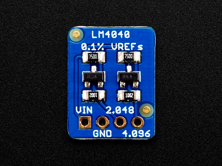
- Noise:Typical 45μVrms(10Hz~10kHz). Adding a 0.1μF low ESR ceramic capacitor further reduces high-frequency noise, and the LM4040 remains stable under all capacitive loads.
- PCB Highlights:
1. The cathode bypass capacitor should be tightly attached to the pins.
2. Use a complete flat surface, with analog/digital grounds separated for single-point connections.
3. There is a Schottky diode between the inside of SOT-23 package pin 3 (NC) and the anode, which must be suspended or connected to the cathode and mustnot begrounded.
4. Use metal film resistors with low temperature coefficients (such as 25ppm/°C) for current-limiting resistors toavoid overlooking resistor temperature drift.
5. Design considerations for driving ADC/DAC
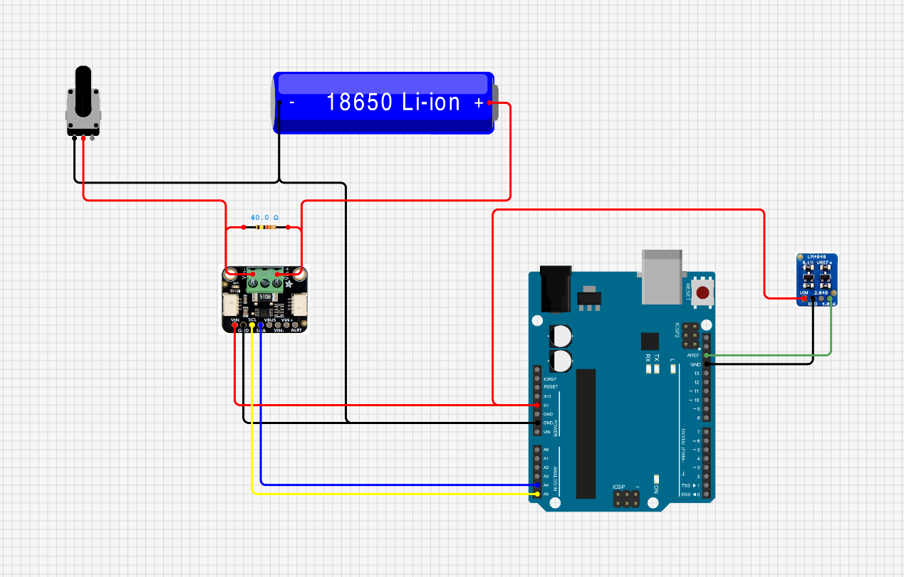
When the LM4040 directly drives the ADC reference input, please note:
- Many ADCs have internal reference inputs with switched capacitor circuits that periodically draw current pulses. It is necessary to ensure that the LM4040 canrespond quicklyand provide transient charge by adding a 10μF + 0.1μF capacitorcombination at the output end.
- If the ADC reference inputcurrent changes sharply, it is recommended to addan op-amp buffer to isolate load changes.
6. Common design errors
Wrong | Consequences | The correct approach |
Only the typical operating conditionRS is counted | Under extreme conditionsIREF exceeds limit or loses power | Double-limit check |
| Reference failure at high temperatures | Refer to the data manual chart |
NC pin grounded | Device damage | Suspended in midair |
Use ordinary thick film resistors forRS | System temperature drift increases by several tens of ppm | Metal film resistors are selected |
7. Summary
The LM4040 achieves excellent DC accuracy at an extremely low cost and with a minimalist circuit. The design focuses on correctly calculating the current-limiting resistor and performing full-condition verification, evaluating the full-temperature error budget, and optimizing noise andPCB layout. It is the ideal choice for portable devices, industrial sensor interfaces, and battery meters that require high precision but a relaxed temperature drift.
Recommend News


Follow Us


-
Phone
400-9682 003