
Xinbole DC‑DC Power Chip Peripheral Inductor Selection Pitfall‑Avoidance Guide
In the field of power supply design, inductors are often underestimated. Many engineers devote most of their energy to DCDC chip selection, yet overlook this tiny energy‑storage component. However, improper inductor selection may push the entire power system into a state of "slow self‑destruction"‑ low efficiency, excessive ripple, chip overheating, and even mass burnout.
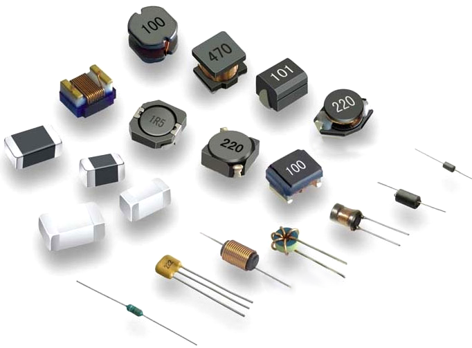
I. How Inductors Affect DCDC
Parameter | Brief Description of Impact |
Inductance (L) | Determines output ripple and load transient response. Too‑low value causes large ripple and instability; too‑high value slows response and reduces efficiency. |
Saturation Current (Isat) | The most critical parameter. Exceeding Isat saturates the inductor, losing energy‑storage capability, triggering current spikes and chip burnout. |
DC Resistance (DCR) | Directly affects conversion efficiency. Higher DCR brings greater heat generation and lower efficiency. |
Self‑Resonant Frequency (SRF) | When frequency exceeds SRF, the inductor behaves capacitively and the circuit fails. SRF shall be more than 10 times the switching frequency. |
RMS Temperature‑Rise Current (Irms) | Exceeding Irms will cause overheating and burnout of the inductor, or accelerated aging. |
II. Typical Consequences of Improper Selection
1. Inductor saturation → chip burnout
When actual peak current exceedsIsat, inductance drops sharply, the switch device bears huge current stress, resulting in chip damage in mild cases and fire hazard in severe cases.
2. Wrong inductance value → unstable output
Too‑low: sharp ripple increase, power supply enters DCM mode and generates EMI issues.
Too‑high: Severe output voltage drop during load transients, feedback‑loop oscillation.
3. DCR too high → sharp efficiency drop
Each 0.1Ω rise in DCR brings an extra 0.1W power loss under 1A operating current.
4. Insufficient Irms → inductor burnout
Even without saturation, sustained operation beyond Irms overheats windings, damages insulation and renders the inductor defective.
5. SRF too low → circuit failure
For high‑frequency DCDC, if an inductor whose SRF is close to switching frequency is adopted, the inductor will act as a capacitor and the power supply cannot work normally.
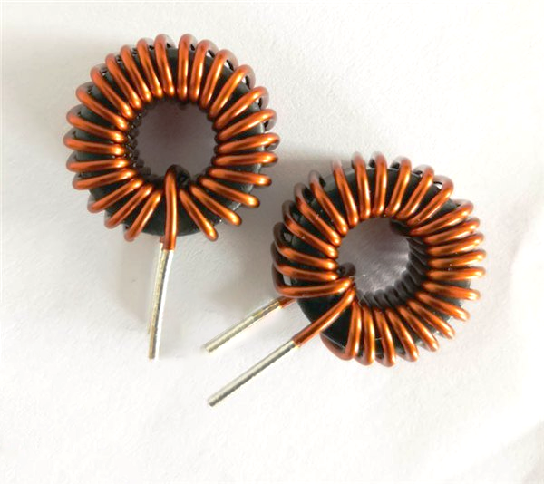
III. Fast Selection Workflow for Engineers
XBWL inductor selection follows the below procedure:
1. Refer to datasheet first: Xinbole DCDC chip datasheets provide recommended inductance ranges; direct reference is the most efficient approach. Do not arbitrarily modify reference‑design values, otherwise loop stability may be compromised.
2. Calculate peak current and reserve margin: Peak current = output current + 1/2 ripple current. Saturation current (Isat) shall be at least 1.3 times peak current. For high‑current applications, a 20%~30% margin is recommended.
3. Balance DCR and efficiency: For efficiency‑critical scenarios such as battery‑powered systems, prioritize low‑DCR inductors. Molded inductors generally feature low DCR and good shielding performance.
4. Check RMS temperature‑rise current (Irms): Ensure maximum operating current never exceeds Irms, and pay attention to PCB thermal layout.
5. Check self‑resonant frequency (SRF): For DCDC with switching frequency above 1MHz, SRF must be more than 10 times the switching frequency.
6. Physical verification: Observe inductor‑current waveform with oscilloscope. Once distortion or spikes appear on normal triangular waveform, inductor saturation occurs. Use thermal imager to monitor inductor temperature; replace immediately upon abnormal heating.
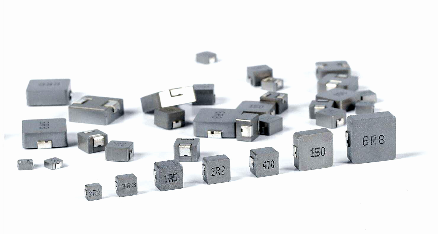
IV. An Easily‑Overlooked Warning
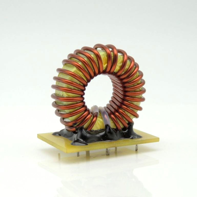
Do not arbitrarily modify inductance values in reference designs. The compensation network of Xinbole DCDC chips is designed for specific inductance values. Arbitrarily increasing or decreasing inductance may cause loop instability and bring output oscillation, voltage deviation and other "soft‑fault" phenomena. Such faults are hard to reproduce at prototype stage yet tend to break out in mass production or high‑temperature environments.
V. Summary
Small as it is, the inductor acts as the anchor for DCDC power supplies. Wrong selection may degrade efficiency and raise ripple in mild cases, or burn chips and delay projects in severe cases. During component selection, engineers shall focus on three practical indicators: saturation current, DCR and RMS temperature‑rise current, and always follow datasheet recommended values. Oscilloscope waveform check and thermal‑imager temperature inspection are effective means to avoid pitfalls.
Recommend News

Follow Us


-
Phone
400-9682 003